Frost that destroys the flowers buds of fruit trees is a recurring problem with severe damage to fruit production. In order to better understand when and where the flower buds are at risk and how to mitigate the damage, the Fruit frost project was started (Clarity on Fruitfrost (4tu.nl)).
Author: Tom van den Berg, University of Twente.
During a calm, cloudless night in spring, the air surrounding the fruit trees can drop below zero degrees through radiative cooling. This results in an inversion layer: a temperature increase with height close to the ground. The air above the inversion layer is warmer. Fans that mix these air layers are most effective if proper mixing is achieved in the close vicinity of the flower buds. Temperature sensors provide insight in these processes but information about the airflow is currently lacking.
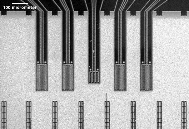
At the integrated devices and systems group (IDS) at the university of Twente, MSc student Daniël Bijsterveld is working on a thermal flow microsensor (Figure 1) to tackle this challenge. The sensor is designed to be sensitive at low flow regimes that are typically found in the canopy boundary layer (< 1 m s-1) and with its small dimensions and low weight it is integrated in the trees environment with minimal effects to the canopy structure and boundary layer. With a dense network of these sensors flow profiles could provide insight in the most cost-effective use of the fans in the orchards.
Additionally, the sensors are also well suited for the greenhouse were gradients in airflow can have a big impact on transpiration and thereby on the productivity of the crops.
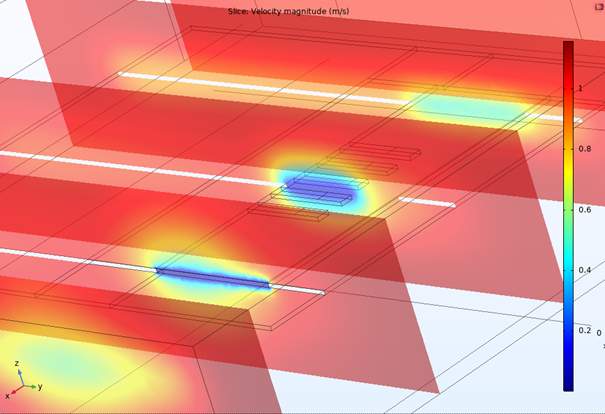
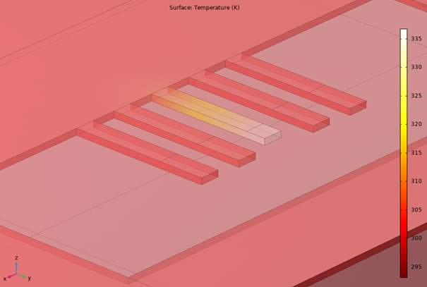
The device can be used as a calorimetric or a hot-wire flow sensor and consists of small heating and detector elements at the tip of the central beam on the chip (Figure 1). Airflow leads to differences in the heat transfer from the heating element to the four detector beams placed on either side of it. Simulations (Figure 2) combined with measurements will provide the input for an iterative design process to produce a final device for field testing.